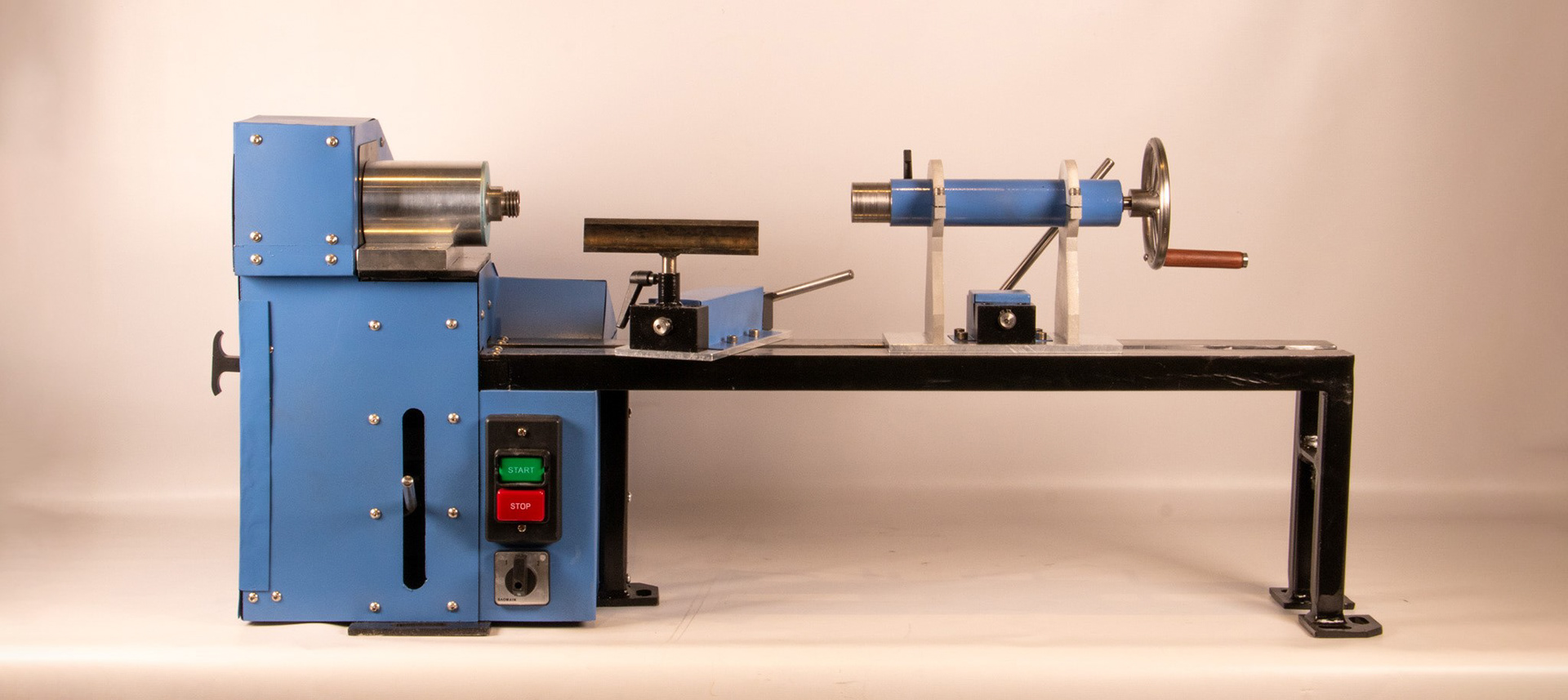
For the final project in my mechanical design class in the Fall of 2023, my team and I spent two months designing and fabricating a desktop wood lathe. Our goal for the project was to create something polished enough to be used in our school's official wood shop and to machine or fabricate nearly every part of it ourselves. I believe we succeeded. As seen in the video below, it can be used to successfully turn pieces of wood with standard tools.
The project involved designing and manufacturing our own welded frame, spindle, transmission system, tool rest, and tailstock. I personally spent most of my time working on the tailstock, transmission, and sheet metal housing. I personally spent my time working on designing the tailstock, speed change system and transmission, sheet metal chassis, and machine bed. I also spent countless hours machining parts on the mill and lathe in all sub-systems of the project. When the class ended I also spent several months of my personal time cleaning up loose ends to get the project to its current polished state. Find out more about each system below!

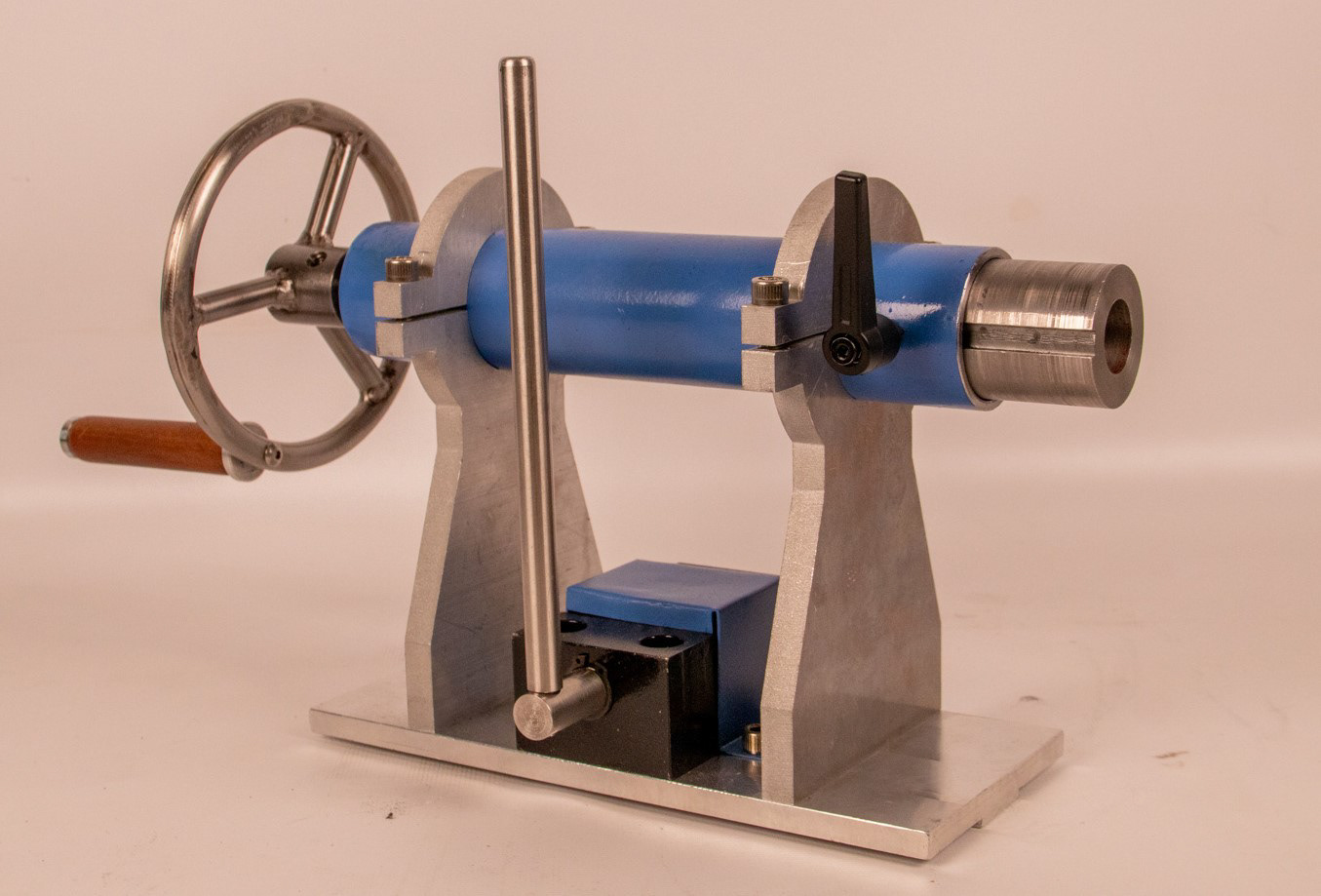
Tailstock:
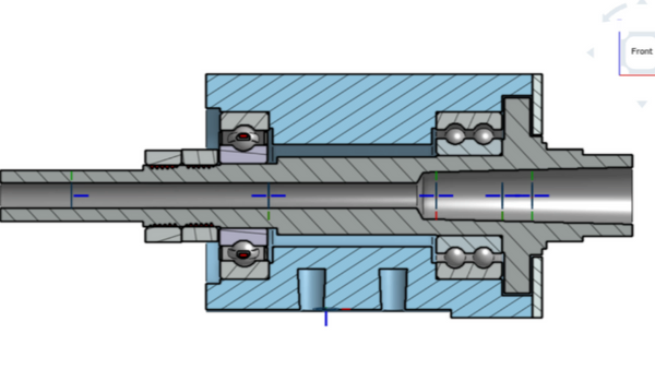
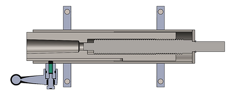
The tailstock of the lathe is primarily used to support the end of the work piece so that it isn't cantilevered off the spindle, and its extendable spindle can also be used for drilling. Inside of the tailstock (seen in the section view below) there is a screw attached to the hand wheel. There are then internal threads on the spindle (the part that holds the workpiece, drill chuck or other tool), so it will slide linearly to make contact with the work piece when the hand wheel is turned.
The tailstock also features a cam-lock mechanism to easily lock it in place on the bed of the machine. When the handle is turned, an eccentric shaft cam pivots and pulls up on a nut sitting under the bed of the lathe. This creates a strong clamping force keeping the assembly in place, locked to the bed
Transmission:
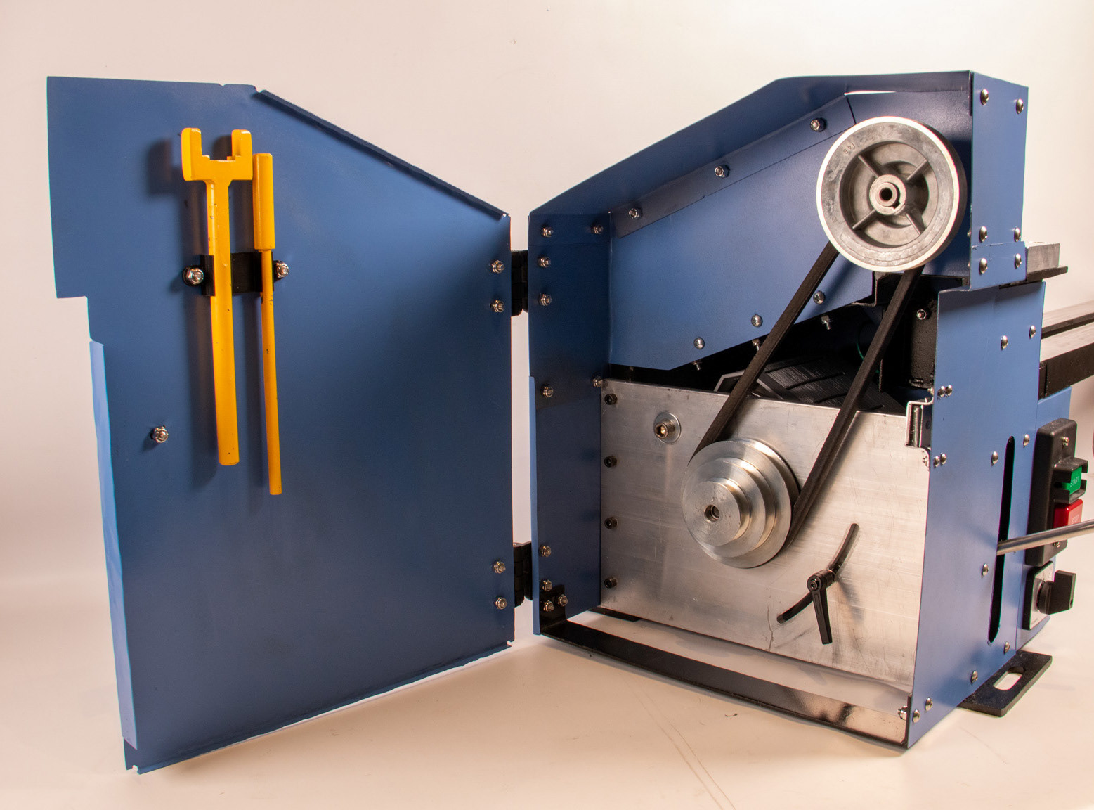
Part of our goal for this project was for our lathe to have a wide speed range and for swapping between speeds to be a simple task. To accomplish this we have a set of step pulleys driving the spindle of our lathe. By moving the belt, one can easily change the ratio of the pulleys and, therefore, speed of the lathe.
To easily change the belt, the entire motor is mounted to a movably plate mounted at a pivot point. The operator can simply open the back of the lathe, loosen the handle holding the plate in place, and rotate the motor about the pivot point to de-tension the belt. A handle attached to the motor sticks out the front of the lathe to make this easier. After that, it is as simple as moving the belt and dropping the motor to re-tension it. The whole process can be completed in less than 30 seconds.
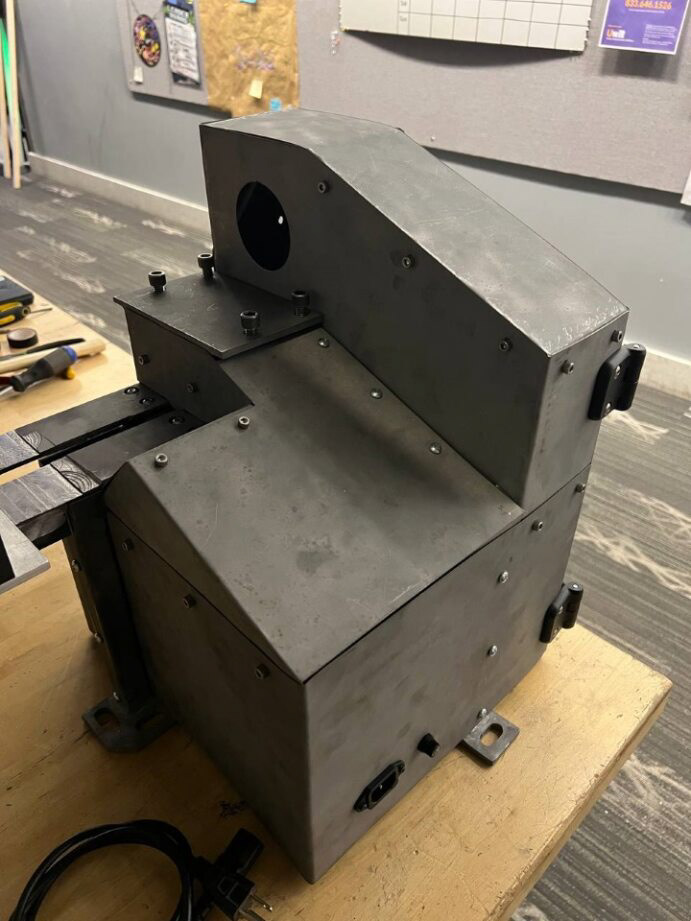
Chassis
It was important that all of our electronic systems be protected from any wood dust and chips that are generated from using the lathe, so I designed a custom sheet metal housing to contain its entire back-end. It also serves to protect the user from the fast moving belt and any electrical systems that could injure the user if handled incorrectly.
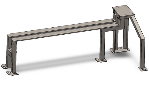
All of this rests upon a welded chassis and machine bed to create rigid mounting points for each subsystem. My group cut and welded the entire frame ourselves and faced the bed ways on the mill to ensure a flat and smooth mating surface for the tailstock to slide along. This includes a slot for the base of the tailstock to keep it properly aligned.
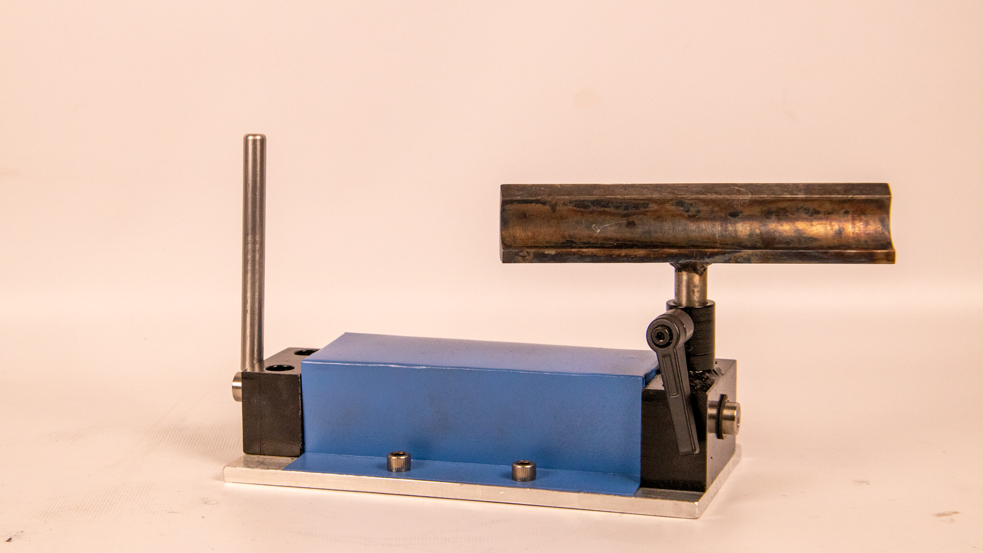
Tailstock:
The tool rest of our lathe exists for the operator to rest their hands and cutting tool upon and keep themselves steady while working. The goal of this system is for it to be highly adjustable and be able to move in several degrees of freedom. Ours accomplishes this by using the same cam-lock mechanism on the tailstock to make the whole base of the tool rest movable and easy to rotate and lock in place after moving. In addition to this, the actual rest section can be adjusted in height and rotated independently of the base.
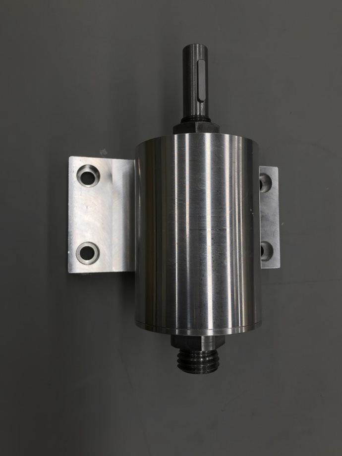
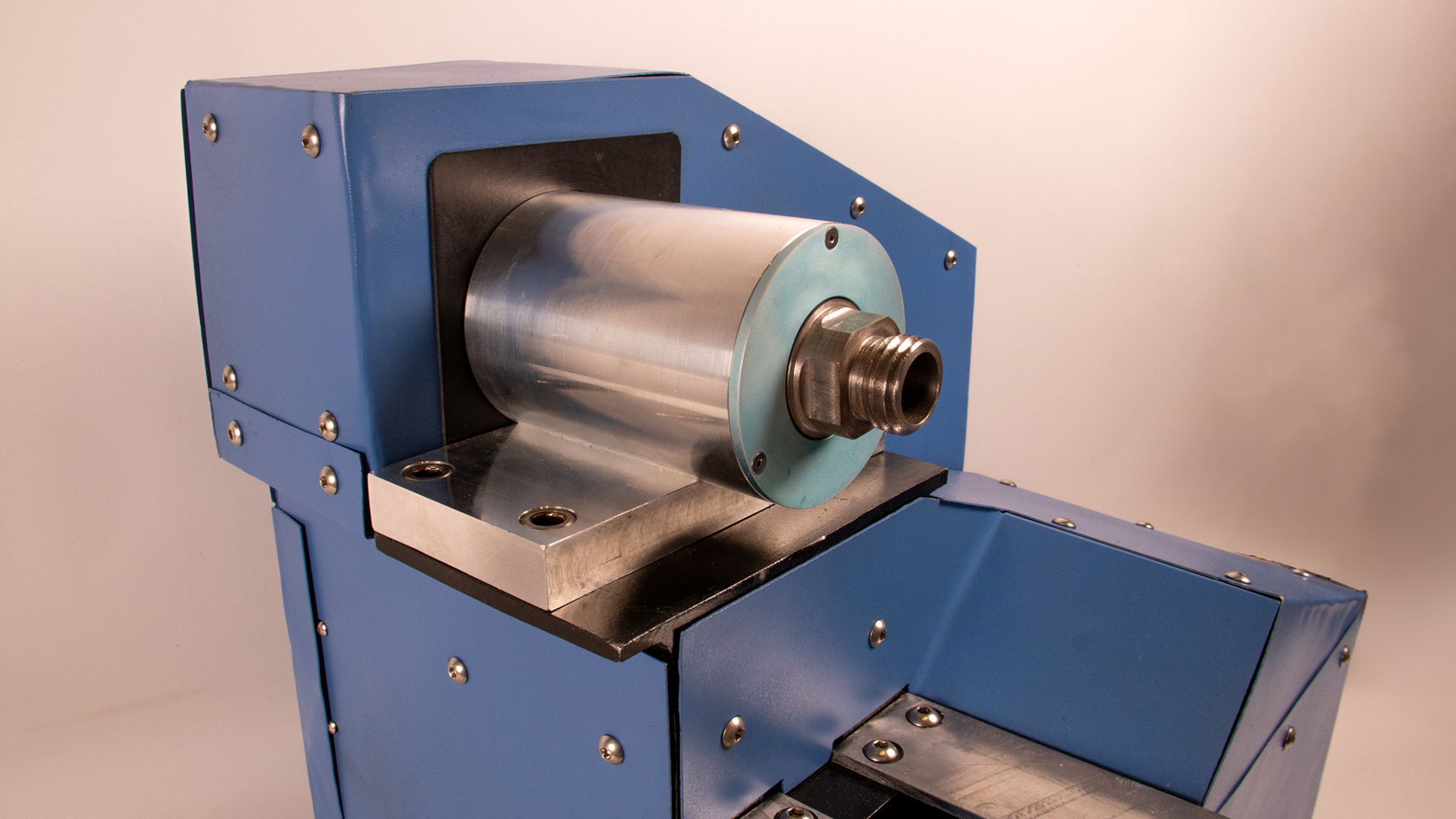
Spindle:
A precise spindle to our lathe was integral to ensure a small degree of runout in parts made on it and to ensure the lathe as a whole could take any cutting or drilling loads put onto it. One integral part in achieving this was investigating bearing selection and layout to find an orientation that was cheap enough to fit within budget but could take both substantial axial and radial loads. If you'd like to learn more, a deep-dive into the spindle design exists on our project website found at the top of this page.