For a class called Mechanical Prototyping I had to complete a "Clockwork Sculpture" project. It was intended to give us experience with simple mechanical systems such as gears, linkages, irises, and more. We were required to create a sculpture that incorporated several of these mechanical systems to create an intricate motion sculpture powered by only one motor. I contributed to most aspects of this project and was largely in charge of designing and constructing the gearbox and wooden structure, as well as integrating the different systems together.
Our clockwork sculpture follows the theme of the popular science fiction show "Doctor Who", as seen from the Gallifreyan (a fictional language from Doctor Who) lettering across the outside of the box along with the TARDIS (a common symbol seen in the show), engraved front and center. In keeping with the science fiction theme, the main feature is an orrery consisting of a solar system model spinning on the front of the box. The sculpture also features and alternating iris system in which a large internal gear sends a small, 3D printed Tardis through the Irises, timed such that the iris and Tardis don't collide.
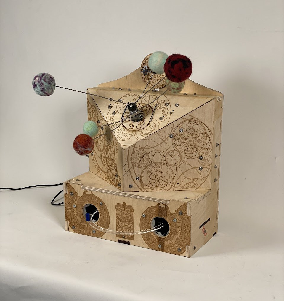
All the unique motion in the orrery described above motion was made possible through a gearbox that takes the single-speed input of the motor and transfers it into three separate speeds which are output through 3 coaxial, concentric shafts. These shafts protrude from the top of the box where they spin 6 planets at 3 different speeds to mimic a real solar system.
Entire sculpture operating
Coaxial shaft gearbox operating
Through a series of gears belts and long shafts power is transferred from the motor to the bottom of the box. Here, a linkage system opens and closes two alternating irises. These are meant to mimic the wormhole created by the TARDIS in the show. Hence, we decided to have a small TARDIS traveling through them on a large internal gear pressed against its driving gear with a set of cams. The irises and TARDIS are timed with the correct gear ratios so that the irises open as the TARDIS arrives at each of them allowing it to seamlessly travel through.
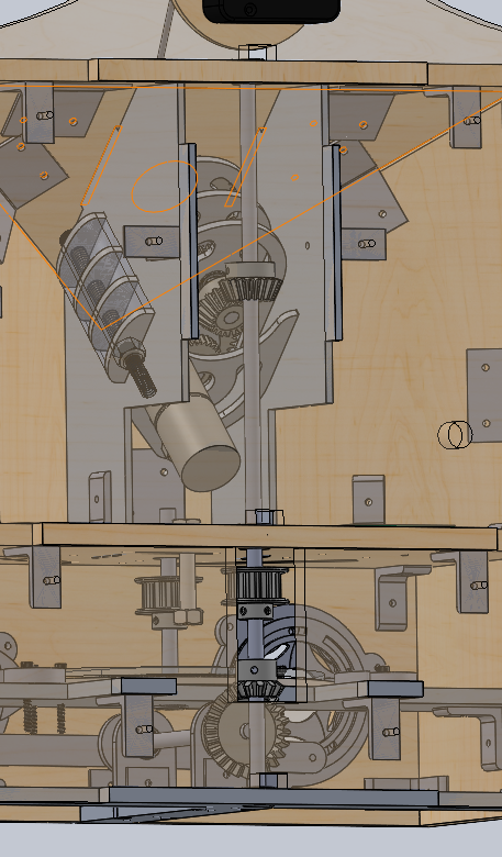
Power drivetrain system visible from the rear
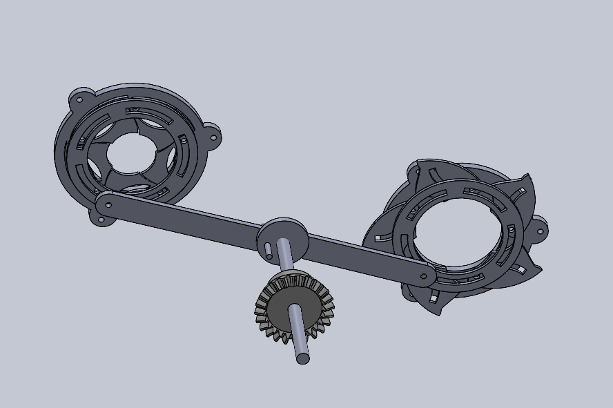
Linkage and Iris system
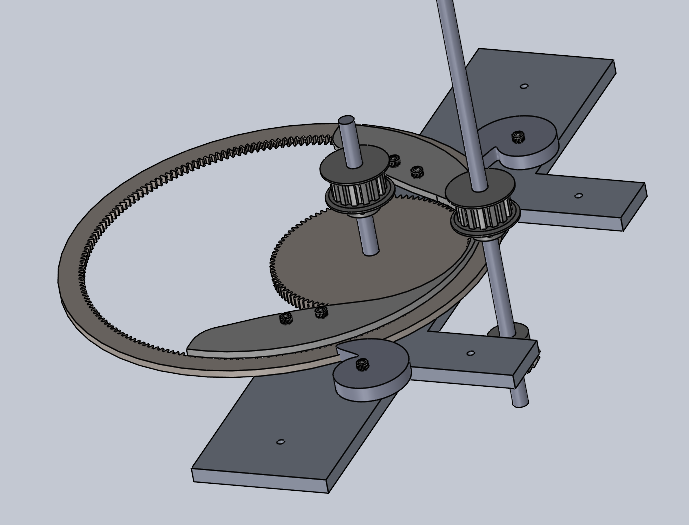
Internal gear and cam pressuring system
In Depth Description:
The flow of rotational power through the sculpture begins with the motor attached to a pinion gear which transfers power to our gearbox with 3 gears of varying sizes on it. Each of these transfers power with a different ratio to the 3 coaxial shafts. The smallest shaft (.25in diameter) receives power at a 1.875:1.125 ratio, the medium shaft (.375in diameter) received power at a 1:1 ratio and the largest shaft (.5in diameter) received power at a 1.125:1.875 ratio. This creates the resulting desired 3 speeds in the coaxial shafts. This whole system is held in place by 4 aluminum plates that fit into 2 larger aluminum plates and are held with bolts and 3-D printed spacers. These 2 plates are slotted into the box structure to hold the assembly, which exists at a 45-degree angle from the rest of the sculpture. This angle was chosen an interesting design challenge and that would be aesthetically fitting. The shafts were constrained by simply press-fitting them into the bearings within these plates (a method of constraining shafts we used throughout the sculpture). The planets on the ends of the shafts are wool felted to create lightweight, and very colorful options between them. These are glued with wires onto some of the gear center bores which are attached to the end of the shaft.
The smallest of the coaxial shafts in the gear box transfers power to a long 12in shaft that stretches the entire height of our inner box through a set of 45-degree bevel gears. The box is split into 2 main segments, an upper one that houses the motor and the gear shaft and a lower one that houses both the iris and the internal gear mechanisms. In the lower half of the box, a set of 90-degree bevel gears transfers power with a ratio of 1:2 to another horizontal shaft which drives the iris linkage system. This consists of two iris assemblies that open and close with a short radial motion. To accomplish this a disk was placed with an eccentric peg on the end of the shaft. This is connected by two linkages that pull and push the irises to open and close them in an alternating motion.
The large vertical shaft also transfers power to the internal gear mechanism through a belt and pulley system. This belt moves across to another shorter shaft that contains a large gear and is tensioned by an adjustable bolt and nut. This gear meshes with a larger internal gear with a gear ratio of 1:2, matching up with the bevel gear ratio below. This way, they move at the same speed allowing for synchronized motion between the two mechanisms. This internal gear is held in place by a large plate to constrain it vertically and two cam-like objects which can be turned and tightened to constrain it horizontally. This gear passes through both Irises and has a small, 3-D printed TARDIS attached to it which is timed so that it passes through the opening iris whilst the other one closes.