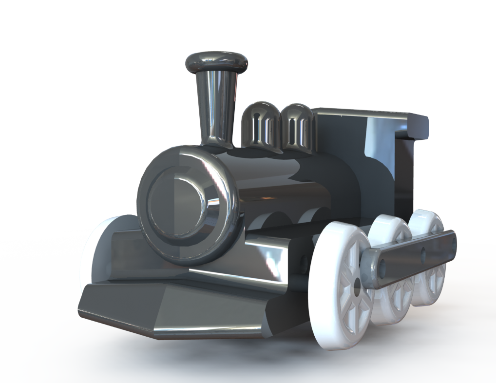
For a Design for Manufacturing Class in Fall of 2024, I designed and built a set of working injection molded toy trains. The task for this project was, in small teams, to design a small trinket using at least 2 parts, one of which being injection molded. After designing the injection molded part we CNC milled the injection molding mold and used it to shoot our designed part an assemble it into several copies of the designed trinket. My and my project partner's goal in this project was to design a working toy train that could be manufactured and assembled cheaply and easily. We accomplished this goal well, building a functional train and establishing a process for injection molding the trains with cheap, easily obtainable parts.
The train is powered with a miniature battery powered motor and is designed to mimic the design of a typical steam engine. The wheels are connected and driven with a linkage mechanism, similar to real trains, allowing for easy transmission of power to every wheel. The main body of the train is injection molded, but the wheels and linkages are 3D printed simply because there was not enough room in the mold to cast more parts.
The train is powered with a miniature battery powered motor and is designed to mimic the design of a typical steam engine. The wheels are connected and driven with a linkage mechanism, similar to real trains, allowing for easy transmission of power to every wheel. The main body of the train is injection molded, but the wheels and linkages are 3D printed simply because there was not enough room in the mold to cast more parts.

Some skills I learned or utilized in this process:
- Solidworks CAD
- Solidworks Plastics Simulation
- Fusion CAM
- Tormach 770M Operation
- Designing parts for injection molding
- Part Extraction
- Fluid Flow
- Mold Machinability
- Designing for integration with off the shelf components
- Mechanical Design & Prototyping
- Solidworks CAD
- Solidworks Plastics Simulation
- Fusion CAM
- Tormach 770M Operation
- Designing parts for injection molding
- Part Extraction
- Fluid Flow
- Mold Machinability
- Designing for integration with off the shelf components
- Mechanical Design & Prototyping
Mechanical Design & Prototyping:
The train body was designed as a shell which is split in two halves. This allows room for the electronics inside and shells will typically give more uniform results in injection molding. It is split in two to remove undercuts with small nubs to snap the two halves together. All faces normal to the split plane were also drafted to allow for easy demolding. All of these design choices combined led to successful molding down the line.
Before reaching the point of injection molding our design, we first had to validate that the mechanisms of the train would allow it to move and that our electronics implementation would work properly. This involved several rounds of iteration on the design of the linkage mechanism driving the train. We discovered that removing as much play from the linkage joints as possible and "quartering" the linkage on both sides of the train offset 90 degrees rotationally from each other allowed the train to move flawlessly. This offset allows for the linkage on one side of the train to pick up the slack when the other reaches at an angle that reduces leverage. A video taken of this first working prototype can be seen to the left.
flOW sIMULATION & Mold Design:
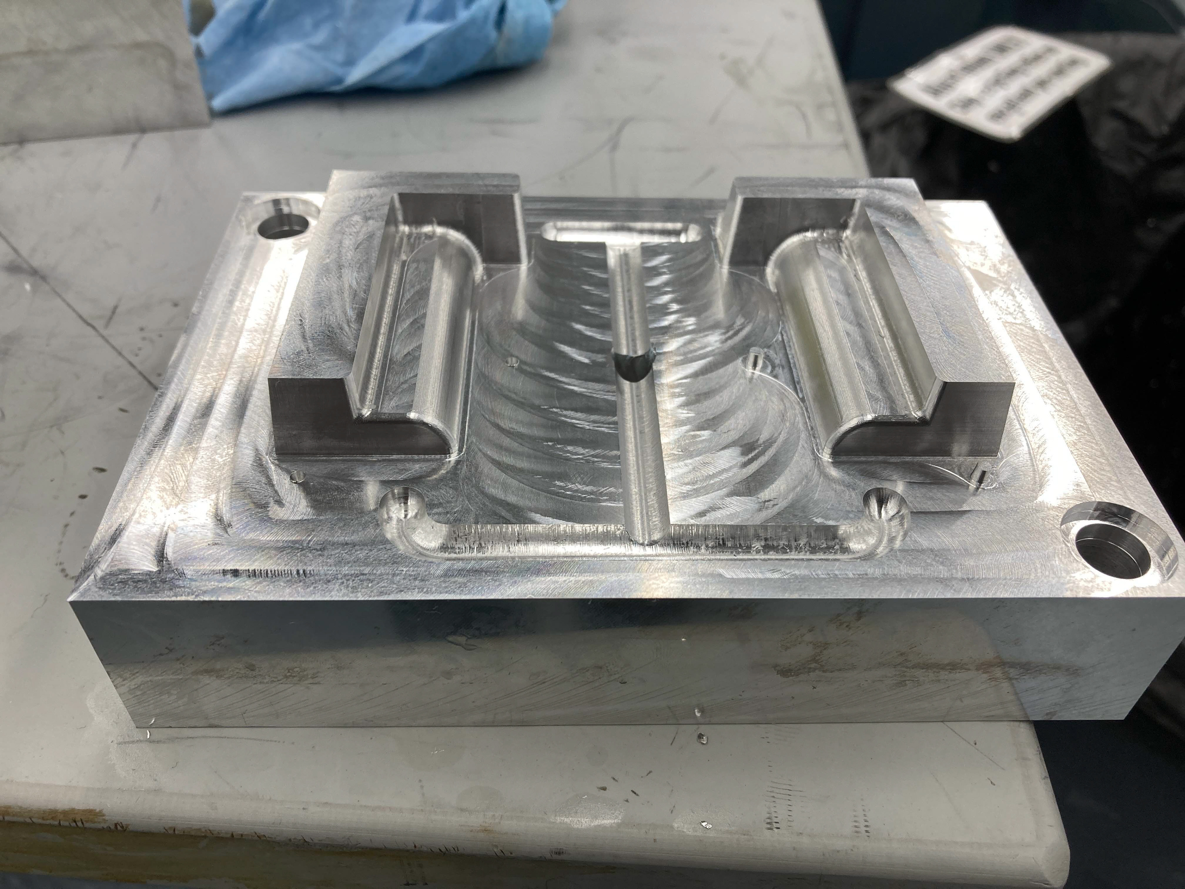
The mold design incorporates both unique halves of the train molded at the same time. It has the flat interface between the halves act as the split line in the mold with the bottom mold having a cavity and the top having an extrusion creating the shell of the mold.
The molten plastic is delivered to to the parts through a main sprue to a series of runners where gates act as a nozzle accelerating the plastic into the part cavity. We were able to determine that the planned mold would fill successfully and where the gates should be located by using a Solidworks Plastics simulation. This simulation checked that the injection pressure and cooling rate were acceptable and estimated a time for the mold to fill. A video of this simulation can be seen to the right.
CAM simulation of the mold being machined.
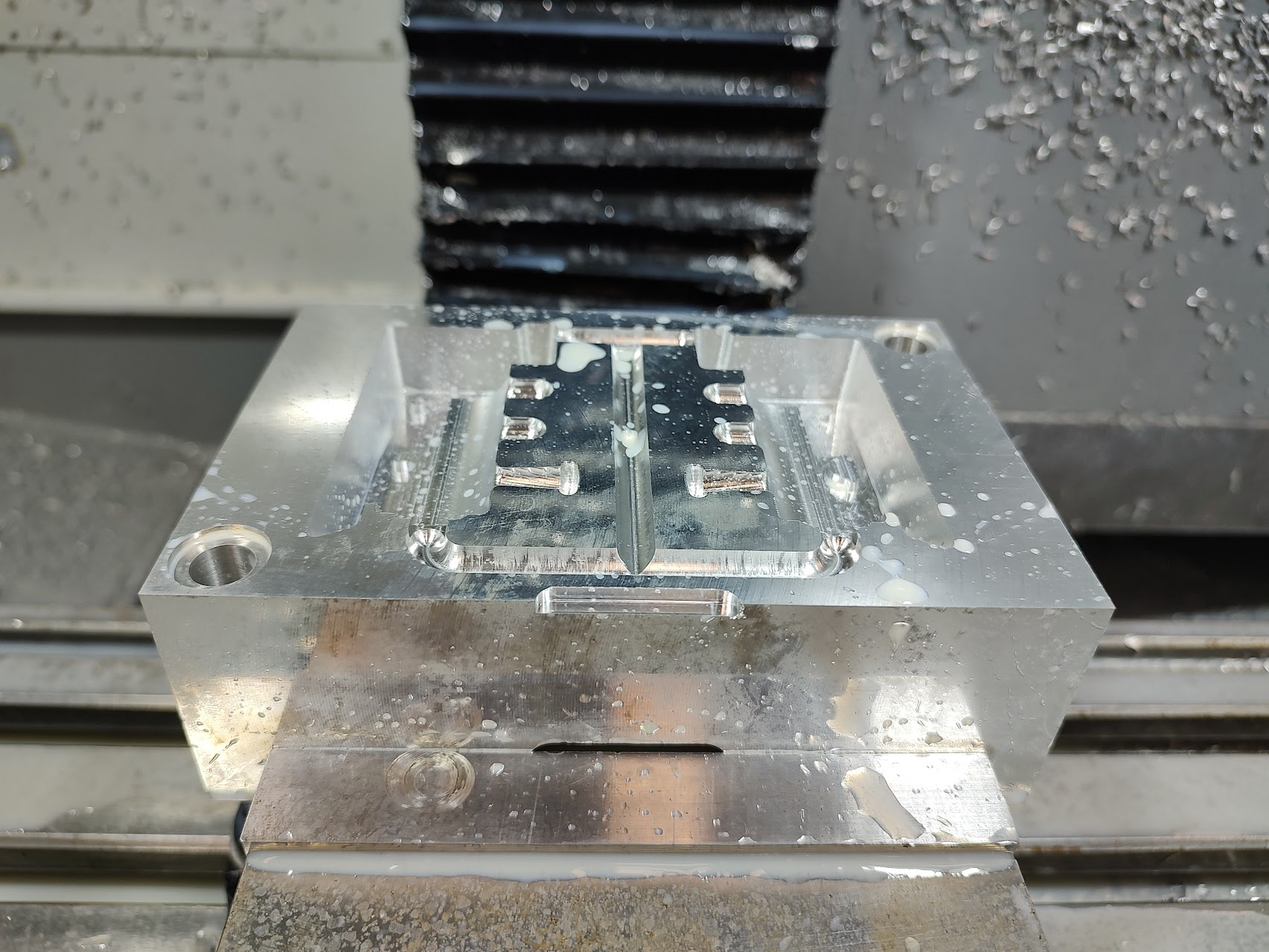
Manufacturing the molds involved creating CAM for the part, then machining a block of aluminum down on a CNC mill. When designing the part we ensured that all geometries could be created with the available tooling which made the machining process quite painless. We used generally advised milling techniques of roughing with the larges tool possible and stepping down to the smallest for small features, contours and finishing passes. For both molds combined, this entailed about 5 hours of machine runtime.
Several features on the mold were designed to be tightly tolerance and in order to create the correct dimensions on the part, we intentionally oversized the mold. This allowed us to measure the difference on the final part from the desired size and adjust it accordingly to ensure proper fits in our parts.
Time-lapse of a portion of the mold machining process.
The molds were designed to have pins located in two opposite corners to ensure proper meshing between the two sides. However, these features were milled in a separate set-up and zero from our actual mold designs. This led to some misalignment within our mold preventing it from pressing closed. Because the tolerances of the mating faces of our mold were quite high this meant we had to play with several diamond pin orientations to prevent the mold from being over constrained. Eventually, we determined that one locating pin was enough and were able to close and align the mold with it in place.
Final Bottom Mold
Final Top Mold
Injection Molding:
Casting the train bodies themselves proved relatively straightforward thanks to all our planning and forethought. We had a bit of trouble honing in the process which could be quite finicky with the older, cheap injection molder we were using. However, once we got the process established, casting parts went quickly and smoothly.
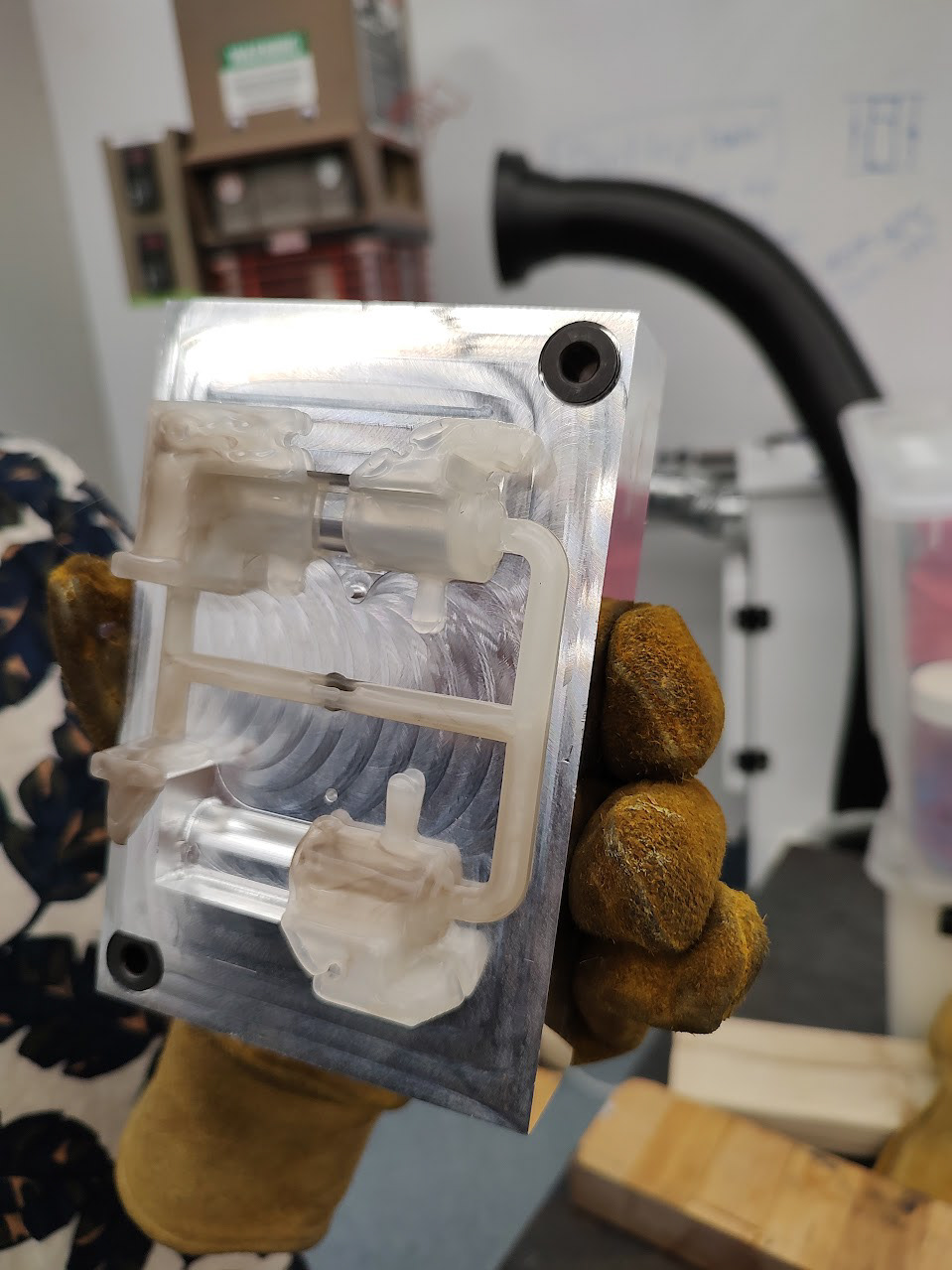
Since the injection molder we used is piston based rather than using a screw extruder, we had a lot off issues with under extrusion into the mold. The less evenly heated and distributed material would sometimes be clumpy and not extrude properly from the nozzle. To fix this, we found that overfilling the machine and increasing the injection pressure allowed for the plastic to fully fill the mold. We also experienced some issues with flashing, especially with the increased pressure in the mold. Increasing the clamping force on the machine and being careful not to shoot too much plastic into the mold managed to remedy this issue as well. Finally, we also had some material issues, we were originally using Polypropylene (PP) to cast our parts, which has a high shrinkage rate. This led to much more sinking on thicker parts of the mold and dimensional inaccuracies that broke our linkage mechanism. Eventually, we switched to ABS which behaved much more as expected producing several perfect train bodies.
Under-exrtuded casting in the mold
An injection attempt that resulted in flashing
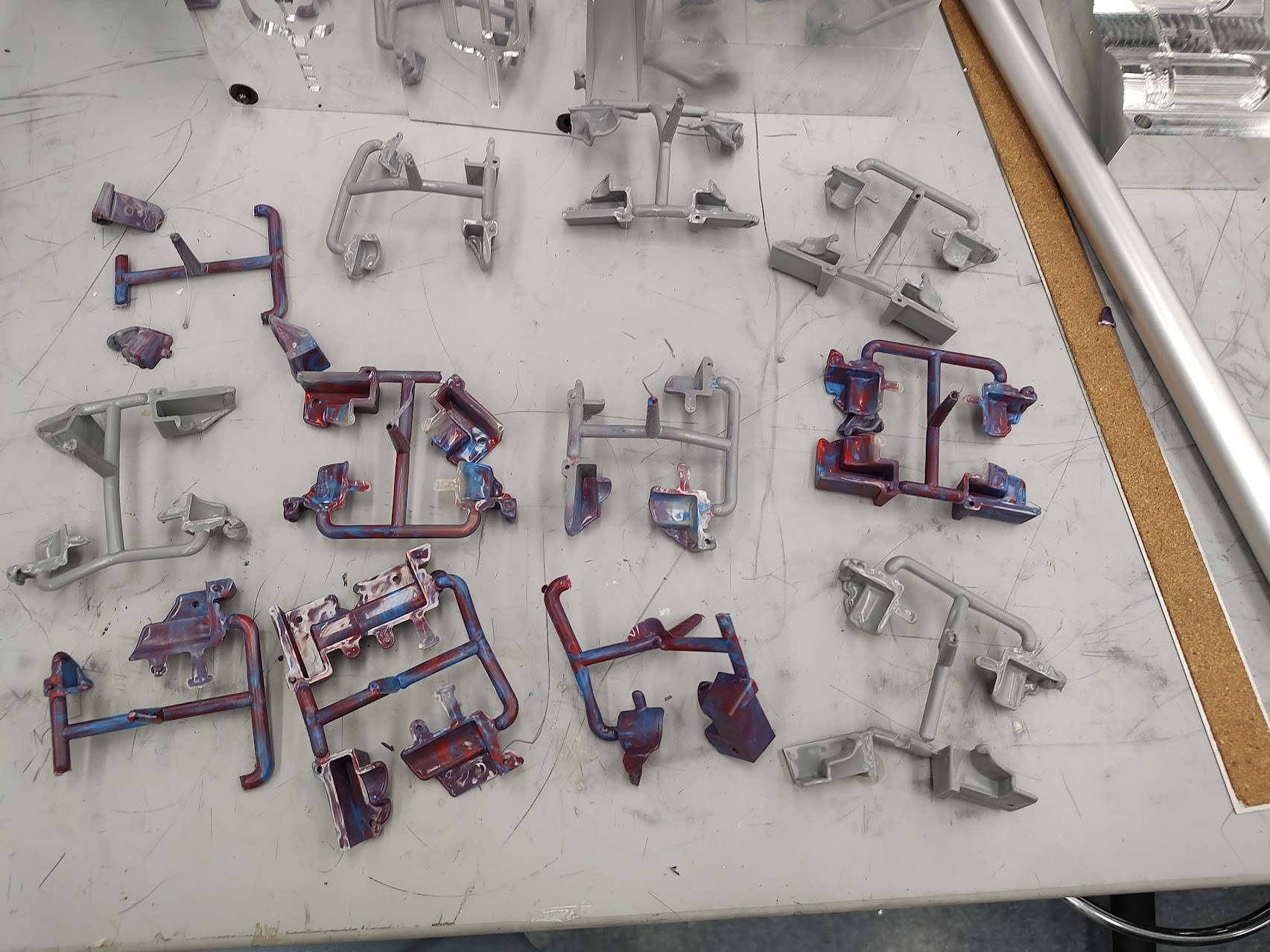
Many of the failed injection attempts
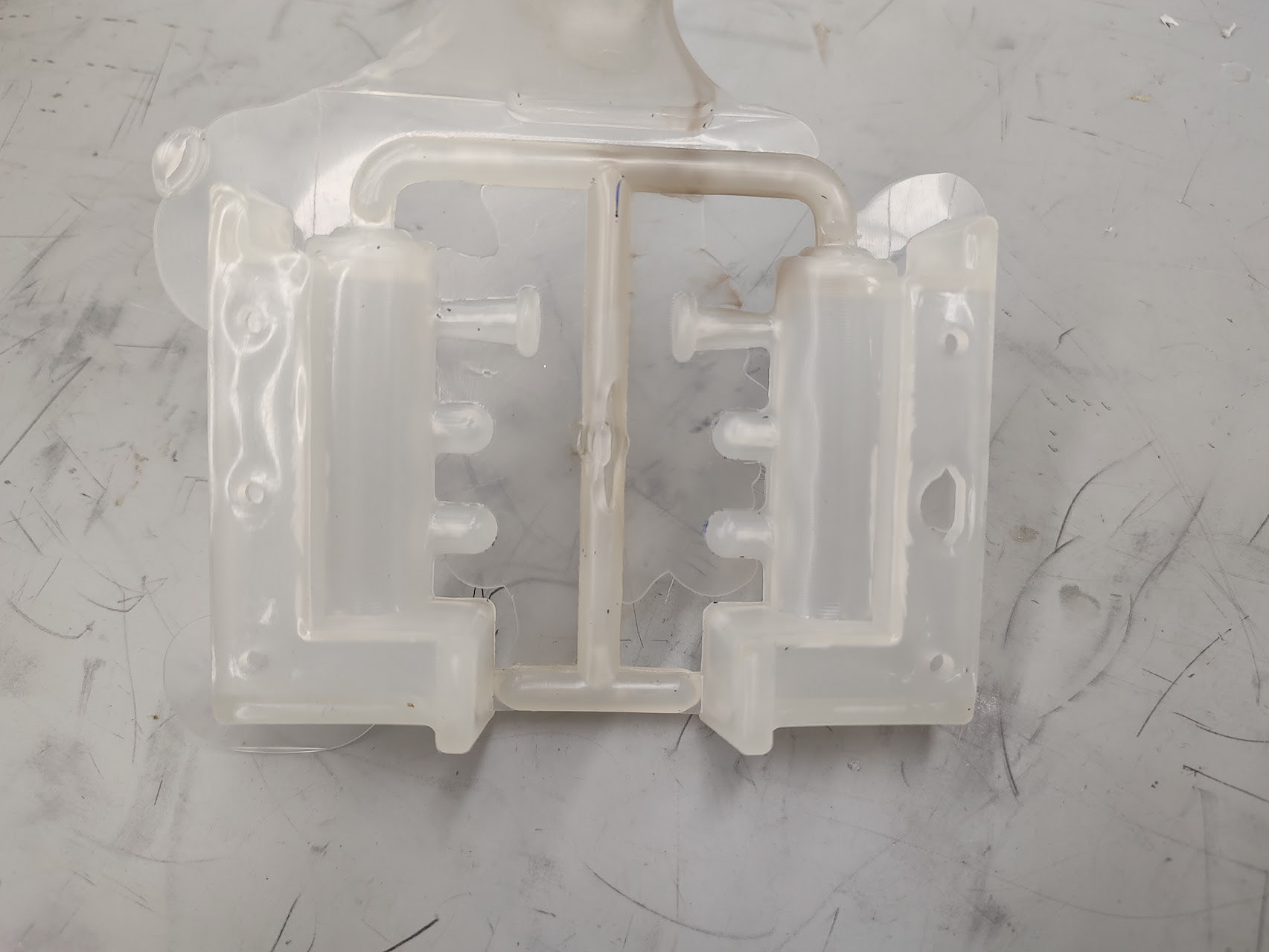
Our fist completely successful ABS part
Additional Details:
BOM:
External Mold Machining Quote: $317.65
Injection molded cost per train:
- ABS Used: ~4^in
- ABS at 1 ton for $1300: $0.10 per part
3D Prints: .432in^3
- At $20 per spool: $0.48
Fasteners: ~$0.30
Electronics:
- Battery Housing x2: $3.10
- Motor: $3.33
- Switch: $0.35
Labor: ~40hrs
- At $50/hr: $2000
Total Initial Cost: $2317.65
Cost Per Train: $7.66
Estimated design and prototyping time: 20hrs
Estimated mold manufacturing time: 8hrs
Estimated time to inject: 1min
Estimated assembly time: 1hr
Estimated mold manufacturing time: 8hrs
Estimated time to inject: 1min
Estimated assembly time: 1hr